- 您现在的位置:买卖IC网 > Sheet目录470 > MAX11014BGTM+T (Maxim Integrated)IC RF MESFET AMP 48-TQFN-EP
Automatic RF MESFET Amplifier
Drain-Current Controllers
Set the LDAC1 bit, D5, to 1 to load the new value of
V DAC1 , upon completion of a V DAC1(CODE) calculation,
into both the channel 1 DAC input and output registers.
Set to 0 to load the new value of V DAC1 , upon comple-
tion of a V DAC1(CODE) calculation, to only the channel 1
DAC input register. Set the T1COMP1/0 bits, D4 and
D3, to control the channel 1 temperature LUT. See
Table 11a. Set the KSRC1-2/1/0 bits, D2, D1, and D0 to
control the channel 1 K parameter LUT. See Table 11b
and the SRAM LUTs section.
Set the channel 1/channel 2 DAC code by writing to the
respective channel’s DAC input registers, DAC input
and output registers, or V SET registers. Write to the
DAC input registers (Table 16) and use a subsequent
write to the software load DAC register (Table 21) to
control the timing of the update. Write to the DAC input
and output registers (Table 17) to set the DAC output
voltage code directly, independent of the software load
DAC register bits. Write to the V SET registers (Table 14)
to include LUT data in the DAC code. Writing to the
V SET registers triggers a V DAC(CODE) calculation by the
following equation:
V DAC ( CODE ) = V SET ( CODE ) ( 1 + LUT K [ K ] x LUT TEMP [ TEMP ])
where
V DAC(CODE) = The modified channel1/channel 2 12-bit
DAC code.
V SET(CODE) = The 12-bit DAC code written to the chan-
nel 1/channel 2 V SET registers.
LUT K [K] = The interpolated, fractional 12-bit KLUT
value. The KLUT data is derived from a variety of
sources, including the V SET register value, the K para-
meter register value, or various ADC channels. See the
SRAM LUTs section.
LUT TEMP [TEMP] = The interpolated, fractional 12-bit
two’s-complement temperature LUT value. The tempera-
ture LUT data is derived from either internal or external
temperature values.See the SRAM LUTs section.
When the KSRC_-2/KSRC_-1/KSRC_-0 bits are set to
000 and T_COMP1/T_COMP0 bits are set to 00 or 01,
the V DAC(CODE) equation simplifies to:
V DAC ( CODE ) = V SET ( CODE )
Note: This is a special case and will not trigger a
V GATE calculation unless a sample already exists. This
functionality should be accessed by the THRUDAC reg-
isters.
For temperature samples or sampled KLUT sources to
automatically trigger V DAC(CODE) calculations, the ADC
must be configured to provide these samples.
Therefore, the ADC conversion register (Table 19) must
have the relevant channel bits set and the ADC must be
in a suitable clocking mode, regardless of the
ADCMON bit setting.
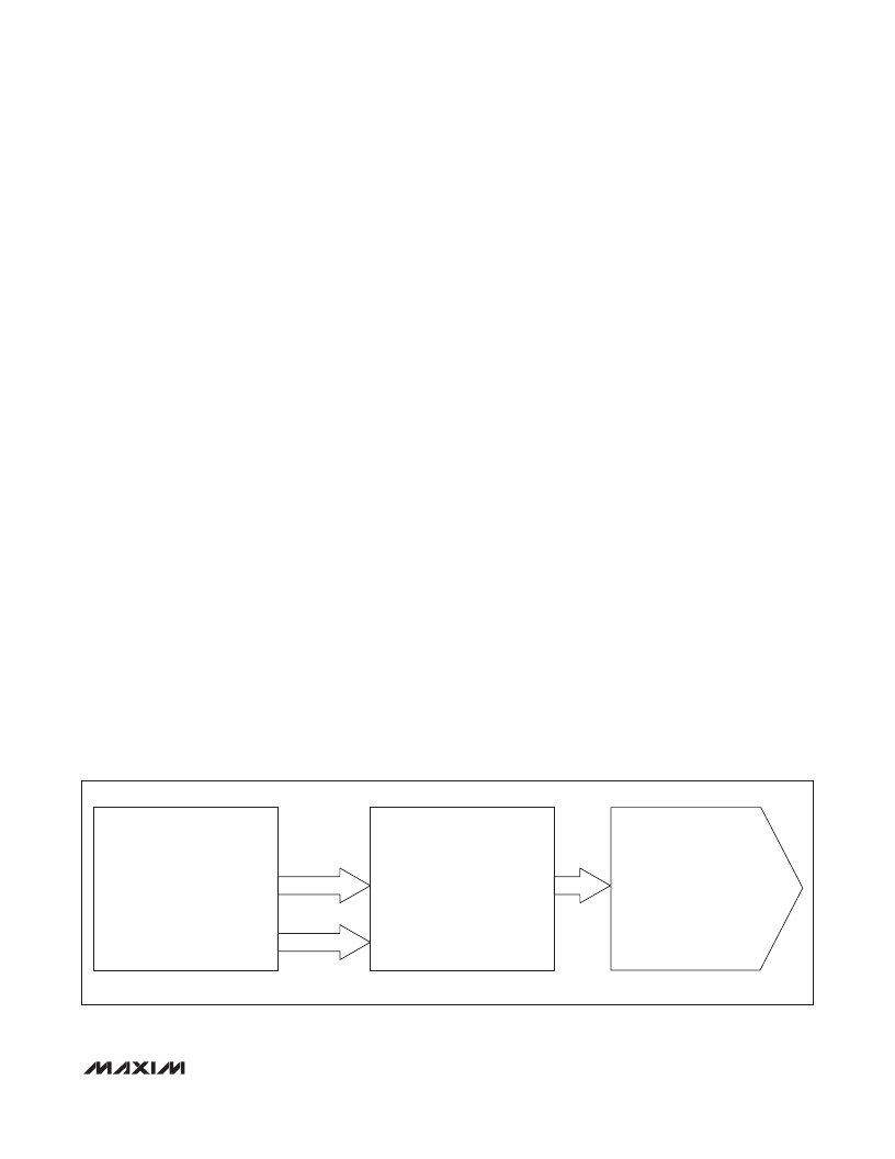
CHANNEL 1/CHANNEL 2 DAC
INPUT REGISTERS:
LDAC
CHANNEL 1/CHANNEL 2 DAC
INPUT AND OUTPUT REGISTERS:
(IPDAC1/IPDAC2
THRUDAC1/THRUDAC2)
REGISTER
CHANNEL 1/ CHANNEL 2 DAC
OUTPUT VOLTAGE
(THRUDAC1/
THRUDAC2)
V DAC CALCULATION
LDAC_ BITS
SET TO 1 IN
SCFG REGISTER
Figure 20. DAC Register Format
______________________________________________________________________________________
37
发布紧急采购,3分钟左右您将得到回复。
相关PDF资料
MAX12000ETB+T
IC AMP GPS FRONT 1575MHZ 10TDFN
MAX12005ETM+T
IC SATELLITE IF SWITCH 48-TQFN
MAX1385BUTM+
IC RF LDMOS BIAS CNTRLR 48-TQFN
MAX1470EUI+T
IC RECEIVER 315MHZ 28-TSSOP
MAX1470EVKIT-315
EVAL KIT FOR MAX1470 315MHZ
MAX1471EVKIT-315
EVAL KIT FOR MAX1471 315MHZ
MAX1472EVKIT-433#
EVAL KIT MAX1472
MAX1473EVKIT-433
EVAL KIT MAX1473
相关代理商/技术参数
MAX11014EVKIT+
制造商:Maxim Integrated Products 功能描述:EVALUATION KIT FOR THE MAX11014 - Bulk
MAX11015
功能描述:射频放大器
RoHS:否 制造商:Skyworks Solutions, Inc. 类型:Low Noise Amplifier 工作频率:2.3 GHz to 2.8 GHz P1dB:18.5 dBm 输出截获点:37.5 dBm 功率增益类型:32 dB 噪声系数:0.85 dB 工作电源电压:5 V 电源电流:125 mA 测试频率:2.6 GHz 最大工作温度:+ 85 C 安装风格:SMD/SMT 封装 / 箱体:QFN-16 封装:Reel
MAX11015BGTM
制造商:MAXIM 制造商全称:Maxim Integrated Products 功能描述:Automatic RF MESFET Amplifier Drain-Current Controllers
MAX11015BGTM+
制造商:MAXIM 制造商全称:Maxim Integrated Products 功能描述:Automatic RF MESFET Amplifier Drain-Current Controllers
MAX11017
功能描述:模数转换器 - ADC
RoHS:否 制造商:Texas Instruments 通道数量:2 结构:Sigma-Delta 转换速率:125 SPs to 8 KSPs 分辨率:24 bit 输入类型:Differential 信噪比:107 dB 接口类型:SPI 工作电源电压:1.7 V to 3.6 V, 2.7 V to 5.25 V 最大工作温度:+ 85 C 安装风格:SMD/SMT 封装 / 箱体:VQFN-32
MAX11017ATL+
功能描述:模数转换器 - ADC
RoHS:否 制造商:Texas Instruments 通道数量:2 结构:Sigma-Delta 转换速率:125 SPs to 8 KSPs 分辨率:24 bit 输入类型:Differential 信噪比:107 dB 接口类型:SPI 工作电源电压:1.7 V to 3.6 V, 2.7 V to 5.25 V 最大工作温度:+ 85 C 安装风格:SMD/SMT 封装 / 箱体:VQFN-32
MAX11017ETL+
功能描述:模数转换器 - ADC
RoHS:否 制造商:Texas Instruments 通道数量:2 结构:Sigma-Delta 转换速率:125 SPs to 8 KSPs 分辨率:24 bit 输入类型:Differential 信噪比:107 dB 接口类型:SPI 工作电源电压:1.7 V to 3.6 V, 2.7 V to 5.25 V 最大工作温度:+ 85 C 安装风格:SMD/SMT 封装 / 箱体:VQFN-32
MAX11019
功能描述:模数转换器 - ADC
RoHS:否 制造商:Texas Instruments 通道数量:2 结构:Sigma-Delta 转换速率:125 SPs to 8 KSPs 分辨率:24 bit 输入类型:Differential 信噪比:107 dB 接口类型:SPI 工作电源电压:1.7 V to 3.6 V, 2.7 V to 5.25 V 最大工作温度:+ 85 C 安装风格:SMD/SMT 封装 / 箱体:VQFN-32
